Procedural Apartment
For my Senior Studio 2 project I wanted a significant technical challenge, but something I know I could take to the next level. This video created for midproject presentations overviews some of the proceduralism available.
For the most part however everything is changeable through the parameter interface, the size of individual types boards, padding values, spacing values, etc. There are a ton of layers also, so make sure to step through and
watch the corner to see how many layers there truly are, some are fairly hard to notice but are very important pieces of the structure.
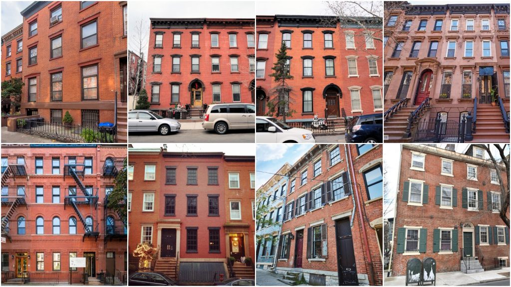
So first thing’s first, need some reference. I wanted a pretty typical, brick apartment building, so that wasn’t to terrible to find. I got a bunch of good reference compiled in a folder to pick out the common elements between them, and those would be the elements included in my project. I wanted to make sure everything was properly labeled as well, so I made sure to do my research on the correct names for various elements. The elements I chose to implement are separate brick sizing from the first floor to the rest of the floors, a “string course” section of bricks in-between these different sized bricks, a top frieze, and dynamic doors and windows.
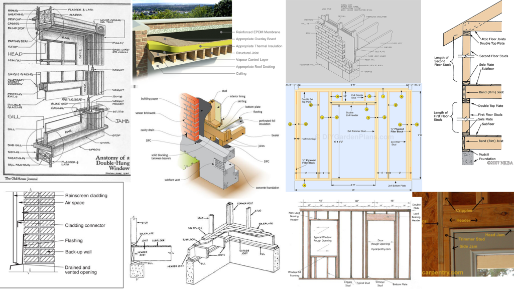
Once I had my style figured out, I needed to do some research on the actual methods to construct buildings. Since this project is meant to be destroyed, we need all the structural details. It took me a little to find the reference I needed, but I was able to compile a file of images that visually labeled and explained how different elements were layered. Since construction methods are typically very similar, I saw very little deviation from good methods, leading me to believe these were the best ones. This was great for my organization and understanding of the structure.
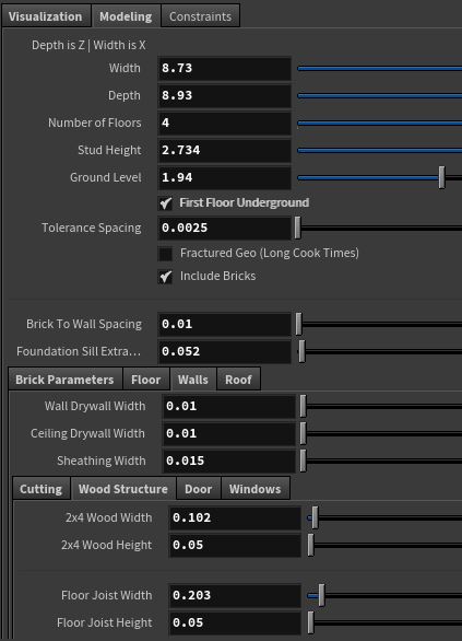
During the process of creating each individual element, I made sure to keep a tidy parameter interface in a single null for ease of use and good organization. I made sure to layer all these parameters on
one another to ensure they would scale properly. This resulted in a chain of cascading logical steps to determine the lengths and sizes of different elements. For example, if you increased the stud height, not only would the studs increase in height and the double header would move up, but that would mean the windows would remain at a centered height in those studs, and that would mean the cripple studs would have to increase in length on either side of the window framing:
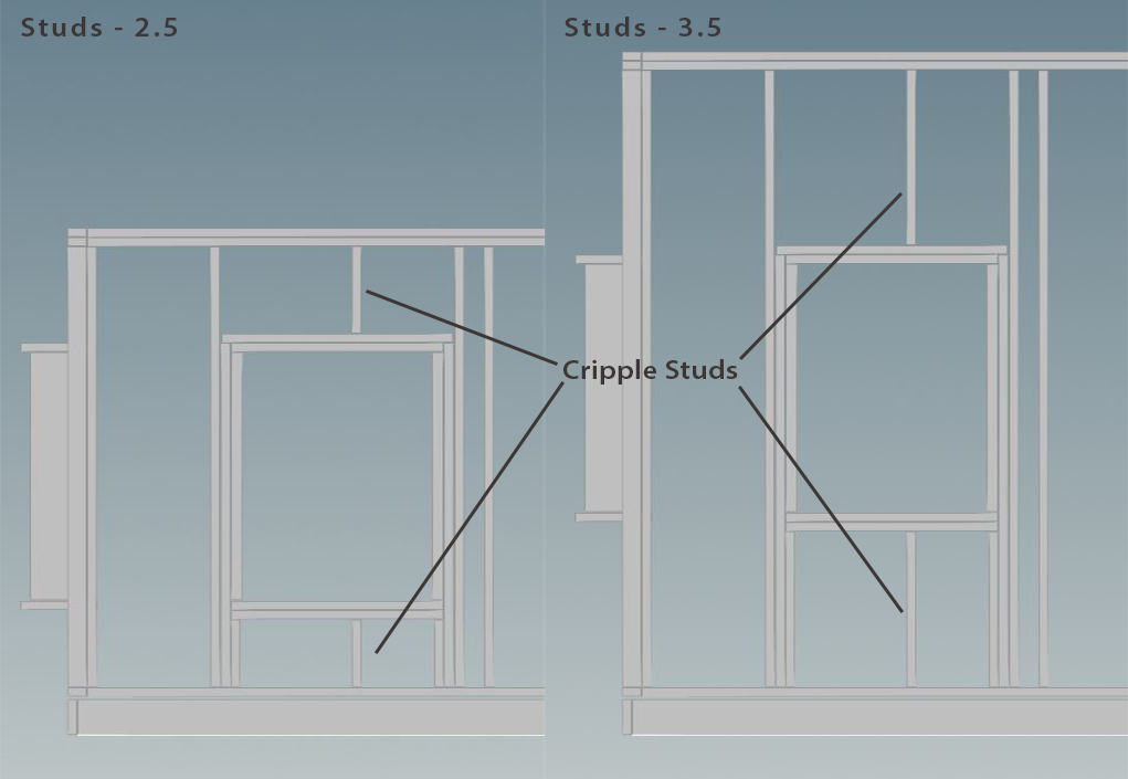
This is a pretty tame example, but now imagine you want the window size to change, want the window to shift, the window framing needs to coincide with the regular wall studs, and on top of all of this you need a standardized tolerance spacing between all elements. It not “hard” by any means, but can get very tedious and complicated when laying out these logic chains across dozens of groups and thousands of elements.
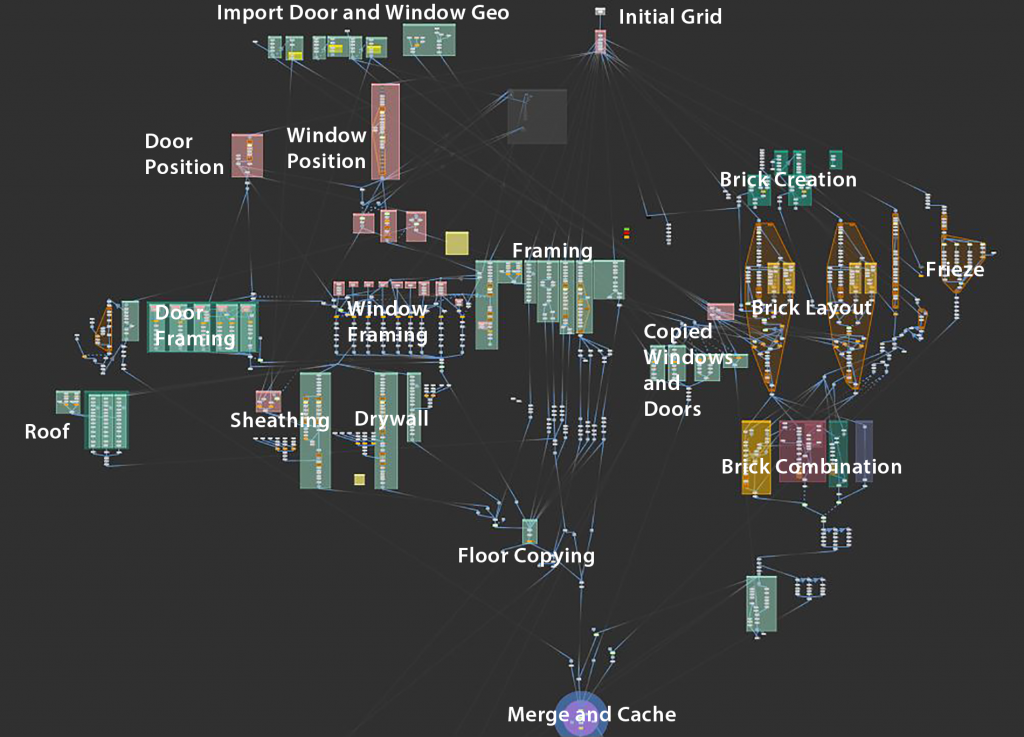
Truly, there are too many elements to go over, but here is the labeled network for creating the geometry as a very brief overview. My basic process was base everything off of the same grid, use some nice
VEX functions to offset and massage the geometry where it needed to be, then layer in the other elements to find it’s place in the logic chain. Easy said rather than done, especially between multiple floors with tight tolerances. If anything overlapped we would get simulation errors down the line, so this really needed to be perfect.
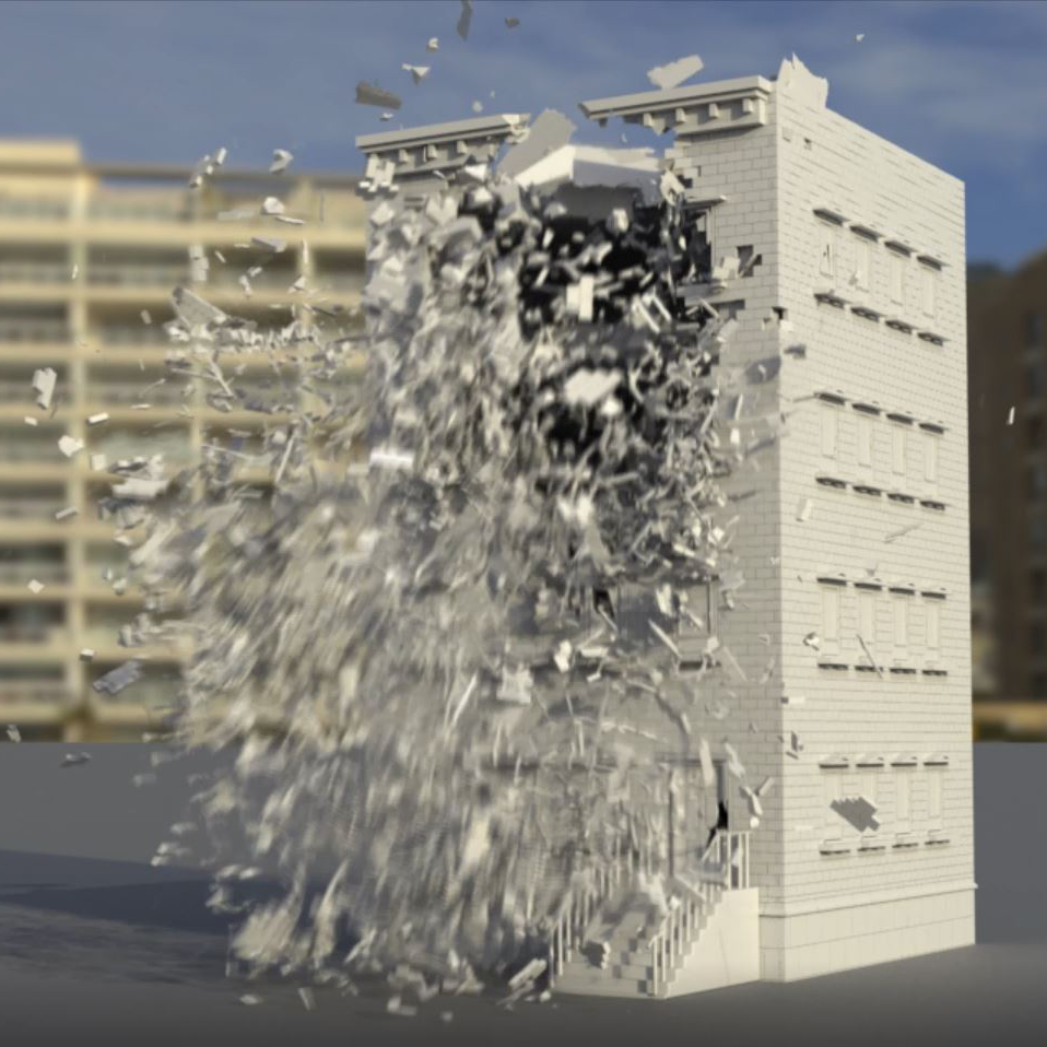
Once the building was created and scaling properly as shown up above (ignoring the fracturing tests), it was time to fracture it.
The fracturing of the pieces were relatively easy thanks to the easy of use with the RBD material fracture node, but my greatest problem was making sure upstream data was carried through downstream, mainly the “name” attributes, which are logically named and placed for ease of reading, and all of the groups so that each piece can be split out and fractured properly. Cleaning up each individual stream was extremely important, but after double checking all of the pieces for matching attributes, data flowed through and splitting out geometry was accurate and fracturing became much more accessible.
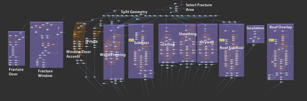
There were a couple of things I am doing when fracturing that are worth taking note of. First off I am selecting a certain area to specifically fracture. This helps with the sim as the not selected geo is then non-active rbds so they are significantly easier to deal with and not worry about any weird Bullet problems, but this obviously speeds up the fracturing process. This lends to faster iterations and when the buildings get quite large it is obviously smarter to only fracture a small part if that is all we would be using rather than spending tenfold the time to wait to fracture. I am completely renaming all of the geometry coming out of the RBD material fracture node to stick with my naming convention for continuity and reliability. After looping all the geo, the constraints and geometry are cached out.
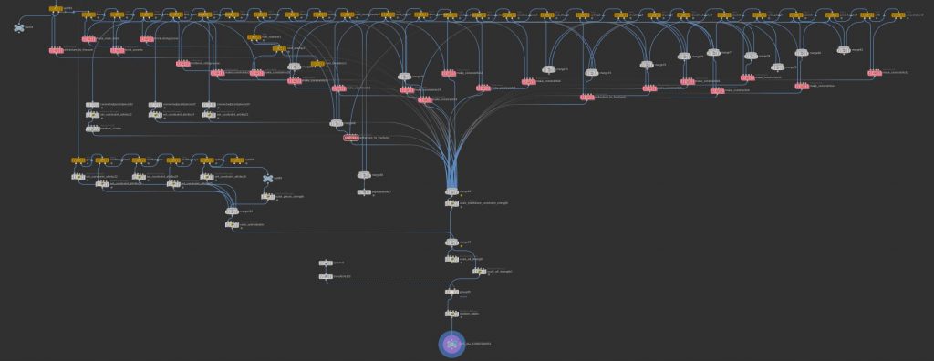
I then take all of the fractured and unfractured geometry together and again split out each group of pieces (studs, door framing, subfloor, etc) and make the correct constraints between the objects. This is all based on how they would accurately be nailed together in construction, so the drywall would be constrained to the studs, but not the bricks. Each of these connections have their own control over strength and a bit of variance.
All of these individual constraint sets get merged together and with the cluster constraints we can just pop it into a DOP net! I was pretty happy with myself when I shoved all these elements into the Bullet Solver in a DOP net and told it to simulate that things didn’t explode immediately but rather acted in a very stable and expected way, The Hires geometry sims plenty fast, the first simulation shown above took only about 5 minutes for 100 frames and the other two took about 10 minutes each for 100 frames. The last bit of the video shows the selective fracturing system I mentioned above, where red would be fractured and white would be static RBD’s.
All in all this was a ton of fun to put together and a great exercise in organization, complexity, and layering. Making sure all the different groups and structural systems worked together properly while also ensuring ease of use was a fun problem to overcome as it kept me in a very technically driven mindset, but forced me to take a step back and look at the big picture when necessary. It was nice being shown that when I take the time to do ensure accuracy that the outcome would show all that hard work. So many elements at play and for a network of thousands of nodes, I couldn’t be more happy with how easy it is to tweak and simulate.